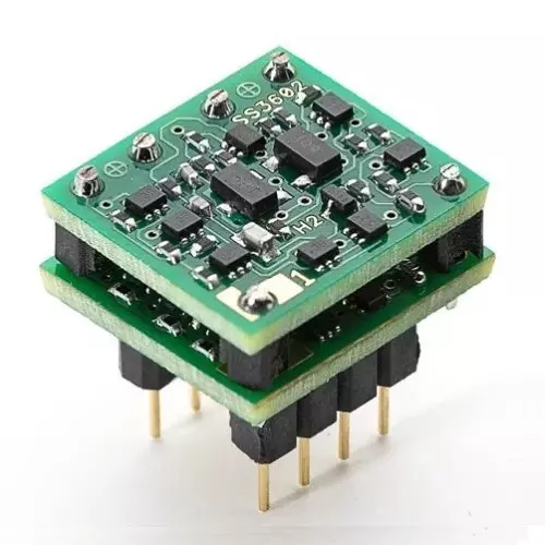
Discrete Op Amps, and why they are superior to ICs.
Introduction: Numerous opinions and preferences exist regarding op amp selection for hi-fi audio circuits. The question we attempt to answer is "Which op amp is the best for audio applications?" We go on Digikey, look up the AD's, LT's, LM's and NE's, and rapidly find our eyes glazing over from specification overload. We read reviews, check out forums, and in our frustration we seek advice from the guy on the right -
Actually, the LM741 is about the worst device imaginable for hi-fi audio use. But then again, he is the most *interesting* man in the world, and not necessarily the most astute at understanding the nuances of op amp selection.
When choosing an audio grade op amp, some opt for high loop gain devices as it is well known that high loop gain makes for a more precise amplifier and lower THD specifications. Others decry the use of high gain devices, claiming the high gain has audible affects, and none of which are desirable. Others want high speed in the form of fast slew rates and wide bandwidths following the old adage that "faster is better." This paper explores the tradeoffs, differences, and inseparable nature of some of these specifications. Op amp compensation techniques, and their affects on speed, gain, and bandwidth will be examined. Short comings and pitfalls will be exposed. Geek out level 9 will be attained. Lastly, a vastly superior alternative to the monolithic (IC) op amp will be revealed.
Background: There is a thing that ties gain, slew rate, and bandwidth together, and that thing is the op amp's compensation. All op amps have it, and the ones that don't are oscillators. In order to fully understand compensation, I must now provide some background for the background.
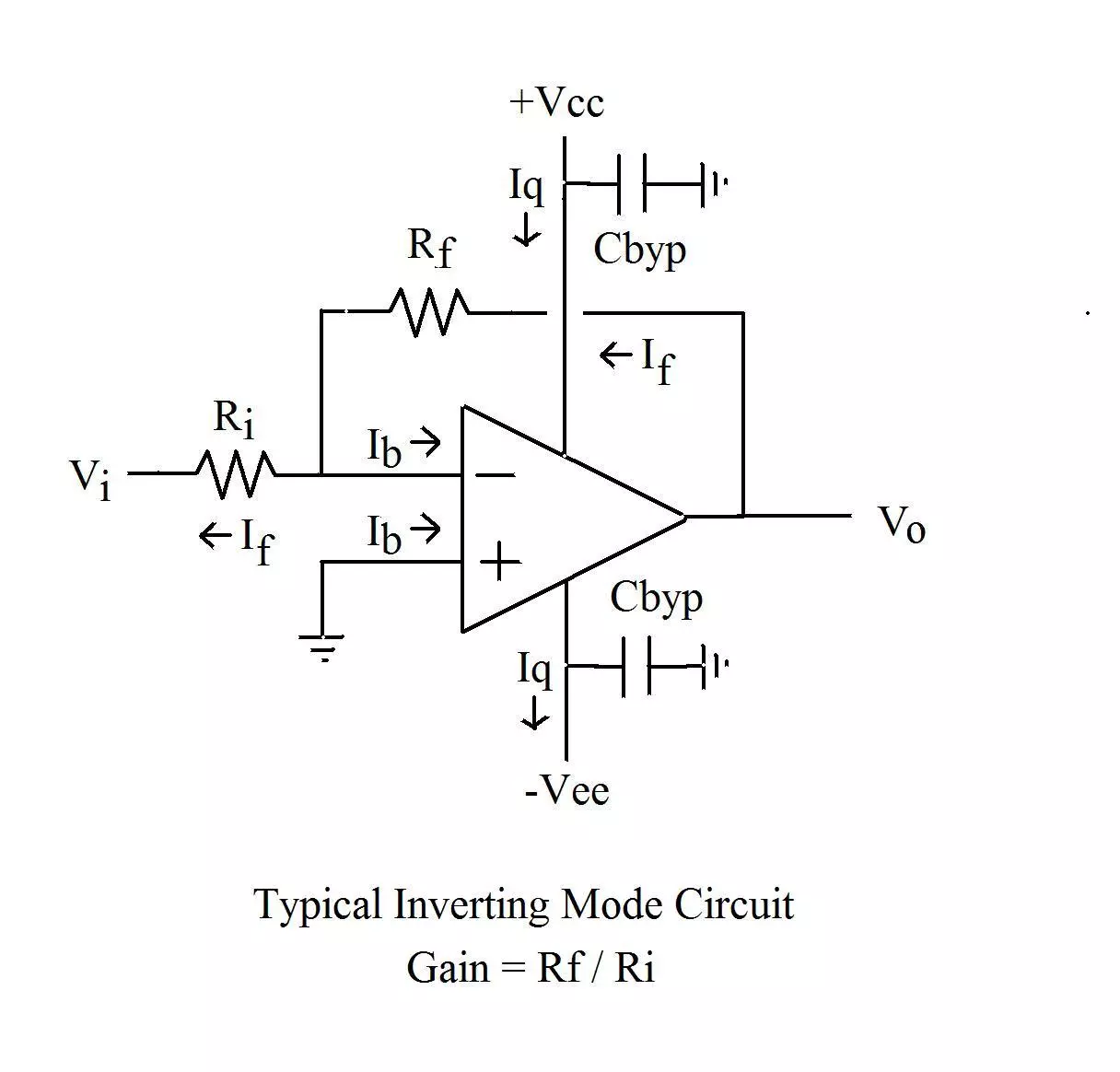
Op amps always operate with some amount of external feedback where some of the output signal is fed back into the input. If we start looking at op amp circuits, we can see how this is being done with feedback resistor RF. To the right is your typical inverting op amp circuit, the gain of which is determined by Rf / Ri. The purpose of the feedback is to set a closed loop gain, and to provide the op amp with a way of “watching its own output” so that its output can be tightly held to a mirror image of the input signal multiplied by closed loop gain. Feedback action is often described as a way for the op amp to “correct itself” when the output signal does not mirror the input, however this is somewhat of a misrepresentation of feedback action as it falsely implies that the op amps output deviated from where it was supposed to be. This isn’t really the case, because the op amps open loop gain prevents such deviations from taking place. A better way to describe feedback action is that it is used to hold the op amps output to a mirror image of input signal, multiplied by the closed loop gain. Exactly how tightly it holds it to it is determined by the op amps OPEN loop gain.
The thing we must be leery of when using feedback, is the phase delay (phase shift, or time lag) that the op amp has. It can't hold its output to a copy of its input if there is a time lag between the two. Unfortunately, all op amps will have some phase lag associated with them, and it is caused by the small parasitic capacitances associated with the transistors that the device is fabricated from. There are several of these stray capacitances, and they will stack up quickly causing a rapid phase shift of hundreds of degrees to occur at the transition frequency of the internal transistors inside the op amp. If the phase lag in the op amp is severe enough, it will oscillate as the delayed feedback signal causes the op amp to chase its own tail, resulting in an oscillation.
In order to prevent this condition and maintain stability, the op amp must not have more than a half cycle, or 180º of phase shift at the point where its loop gain has fallen to 0dB. This condition is called Nyquist stability criteria, and frequency compensation is employed to ensure it. Compensation works by employing a single, dominant pole in the device that hits first, and will come long before the phase delays that come from internal parasitic capacitances have any affect. This single pole will systematically burn off (or reduce) the gain, and push the gain below zero before the subsequent poles come into play, and stability will be maintained. This is what compensation does. It ensures that there will not be a phase shift of more than 180º while the op amp still has open loop gain. Refer to the plot on the right to see an uncompensated amplifier, and one that uses compensation.
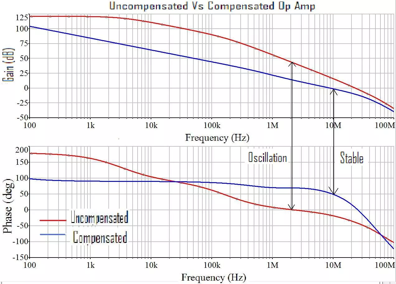
As one can see, the uncompensated amplifier (Plotted in red) has accrued over 180º of phase shift (From 180º down to 0º) while it still has around 40dB of open loop gain present. When its loop gain finally crosses 0dB, there is around 230º of phase shift that has occurred. This point on the graph is marked “oscillate” and the amplifier in question here will undoubtedly do just that.
The compensated amplifier plotted in blue only has about 130º of phase shift at the point when the gain falls to zero. This amplifier will be stable, and can be said to have 50º of phase margin. (Phase margin is the amount of phase left over out of the 180º that is necessary for stability when the gain crosses 0dB) Compensation is what makes this possible. You can see that the compensated graph in blue has a very orderly slope of 6dB / octave, and a phase shift of around 90º over most of the frequency range. This is the characteristic of a single pole roll off. It is created by a single capacitor purposefully placed inside of the device to roll off and reduce the gain to zero before the poles from the parasitic capacitors internal to the op amp come into play. It has the same effect as a single pole low pass filter, and in a sense, that is exactly what it is. Every op amp ever made uses this technique to maintain stability. They use a single pole compensation scheme, and they will all have a loop gain plot that always falls at 6dB / octave.
A Realization: Since IC op amps use single pole compensation and therefore have a 6dB / octave gain roll off, it is possible to plot the maximum theoretical gain that could ever exist at any frequency, knowing only the bandwidth. We simply draw a line up from the unity gain bandwidth point at a 6db/octave slope, and we can see right away how much loop gain is possible at any frequency. An example of this appears to the right.
Three hypothetical amplifiers are presented, with unity gain bandwidths of 1, 10, and 100MHZ. This plot shows the maximum theoretical gain that any of them can have at any frequency. Keep in mind, this plot is for a MAXIMUM possible loop gain. A given device may well have less gain in the low frequency (10 – 100Hz) region where loop gain typically tops out.
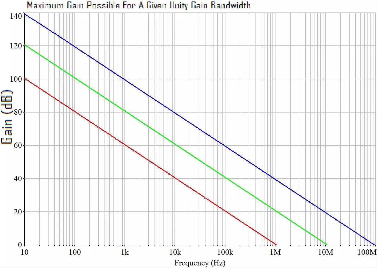
The point here is to illustrate how unity gain bandwidth sets an inherent cap on how much gain is possible given a single pole compensation scheme. For example it is impossible to find a 10MHz single pole compensated op amp with 80dB of gain at 10KHz. The nature of the compensation scheme would limit said amplifier to around 60dB of loop gain at that frequency. Keep in mind too, that when an op amp datasheet specifies the loop gain, they are specifying a MAXIMUM, which usually occurs at ~100HZ or less, and it’s usually specified at DC. The fact that the gain drops at 6dB per octave is assumed to be known by the reader, and often goes unmentioned by the author of the device datasheet. The point is that a 10MHz op amp with a specified gain of 100dB in the datasheet will still only have 80dB of gain at 1KHZ, 60dB at 10KHz, and so on, whether the datasheet spells this out or not.
Its not the bandwidth you seek: So why don’t we just select the highest bandwidth device possible knowing that we are also maximizing loop gain in the audio band at the same time? Well, because high bandwidth devices are finicky creatures. By causal inspection, it would stand to reason that we don’t need a 100MHz op amp to amplify audio signals in the 10’s or even 100’s of KHz region. And that is true, we don’t. Granted it’s nice to pick up the loop gain that is inseparably linked to the bandwidth, but the high bandwidth itself isn’t needed, and in fact becomes problematic the higher it gets.
If you read the datasheets of high bandwidth devices, you will begin to notice all sorts of extra things and special precautions that one must start paying attention to in order to successfully use them in your circuits without oscillating. For example, they usually require extra power supply bypass capacitors on their power pins. Some manufacturers recommend an array of them, comprised of tantalums, ceramics, and a small NPO for high frequency decoupling. None of these high speed devices are recommended for use in DIP sockets, as the inductance of the socket is enough to upset the delicate balance that must be maintained to ensure stability. Most of these high bandwidth devices specify a maximum value of feedback resistor that can be used, and its typically less than 1K. This is because the feedback resistor will form an extra pole (and add extra phase shift) with the input capacitance of the device. The parasitics of the board layout must also be taken into account. A few tenths of a PF of stray capacitance on the input pins are enough to send a 100MHz op amp into a tizzy. And if you plan on driving ANYTHING that even remotely resembles a capacitive load, forget it. In short, high bandwidth devices do not drop into audio circuits with DIP sockets well.
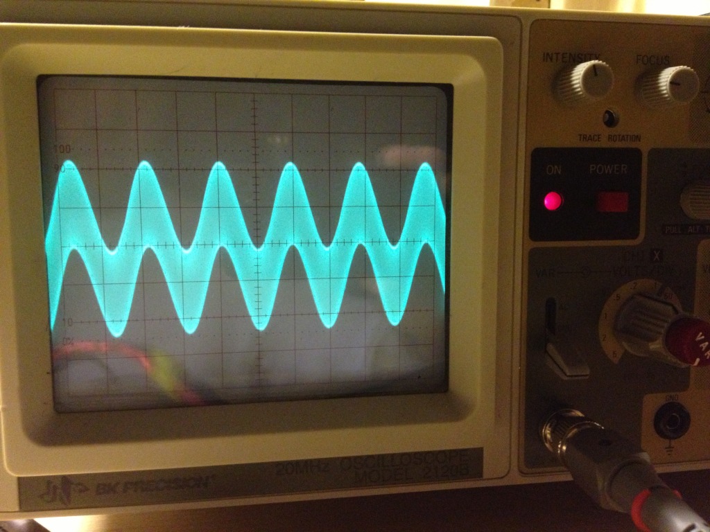
When the bold do attempt to put such a device in their system, more often than not the device will have a low level oscillation in the MHZ region, yet still play audio signals. It will just sound like crap due to the oscillation. To see what this condition looks like on an oscilloscope, refer to the picture on the right.
Here we can see an audio signal, with a bunch of high frequency “fuzz” (the oscillation) riding on top of it. This is why high gain devices receive minimal praise in some audio circles. It’s not the gain at all, but rather the high bandwidth and associated temper mental nature of such a device. These devices will often oscillate in the MHz region when used with DIP sockets, feedback resistors of a few K ohms, leaded bypass capacitors, and PCB’s without ground planes. The oscillation from the high bandwidth is what causes the terrible sound. It doesn’t have anything to do with the gain. If one doesn’t have an oscilloscope with adequate bandwidth, you might not ever know that the oscillation is even happening. Even though gain and bandwidth are inseparably linked, in this case, it’s the bandwidth to blame, not the gain.
Its not the slew rate, either: Fast slew rate devices are a favorite among audiophiles as well, and fast slew rates are usually associated with wide bandwidth devices. There is an equation that can be used to calculate the slew rate requirement of a device if we know the maximum frequency and the peak amplitude of the signal that the device must amplify. This equation is –
Required Slew Rate (in V/µS) = 2π F Vpk / 1,000,000
We divide by 1 million to get an answer in volts / microsecond. If we omit the division by 1 million, our result will be in volts per second. Slew rates are typically specified in volts per microsecond, so we shall divide by one million to obtain a result in those units.
So let’s bang out some math, and see what we get. Most op amps in line level circuits process signal amplitudes of a few volts peak. Typically, these op amps are supplied from something like ± 15 V, so it’s impossible for them to process signals much beyond 10 or 12 volts peak anyway due to the limitation of the power supply rails. (Headroom) The upper limit of audio frequencies is widely considered to be around 20KHz, but let’s be obnoxious with this too, and call it 160KHz, which is 3 octaves higher than is presumed to be audible by the human ear. So how much slew rate is required of an op amp to reproduce a 10V peak signal at 160KHz? Turns out, its 10V/µS. Pretty slow, right? If we get more reasonable, and calculate a slew rate requirement for 5V peak at 50KHz, we only need a paltry 1.5V/ µS slew rate device to accomplish this.
Under mathematical inspection, it would appear that excessive slew rates, just like excessive bandwidths, are not needed for audio signal amplification. The reason that so many audiophiles choose these devices and think they sound good is due to the associated loop gain of such devices, as it has been demonstrated that the high speeds and bandwidths aren’t really buying them anything. What they *are* getting that they like, is the higher loop gain in the audio band.
So where do we go from here? Seems like we are stuck, Right? If you want high loop gain, you will only get it with high bandwidths and slew rates, and we will just have to deal with the cantankerous nature of such devices. If you like low gain and high speeds, you’re doubly screwed. Can we have it all? Can we get radically high loop gains with reasonable bandwidths? Can we compensate our op amp to have a roll off steeper than 6dB / octave?
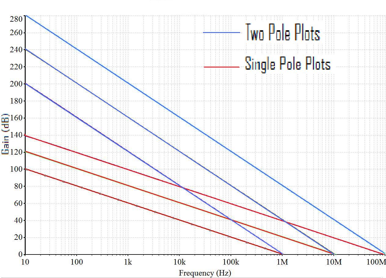
Two Pole Compensation: If we could compensate our op amp using a two pole roll off rather than a single pole, we can double the slope of the gain plot to 12dB / octave. Suddenly, much more gain would be theoretically possible at any frequency, which is nice, because that is what we are after anyway. So what would this look like?
The loop gain plot on the right shows 6 hypothetical op amps with bandwidths of 1, 10, and 100 MHz compensated with a single pole and a two pole scheme each. It can be seen that for a given bandwidth device, there is far more loop gain that is theoretically possible using two pole compensation due to the steeper gain roll off. Suddenly, a 1MHZ two pole compensated op amp will have just as much gain at 10KHz as a 100MHz device compensated with a single pole. Below 10KHz, a two pole device has more gain still than its single pole compensated counterpart.
So can we do this? Can we get an op amp with 2 pole compensation and have massive loop gain and a reasonable bandwidth ? Yes we can, but you won’t find it in a monolithic IC.
Monolithic IC's pretty much all use single pole compensation because the capacitor required to implement it is small and there is only one of them required. Putting capacitors inside of IC's is a tricky business, as the capacitor consumes a large amount of the space inside of the IC. Its capacitance value must be kept small in order to make it fit. Two pole compensation is nearly impossible to implement in an IC, because it requires at least two capacitors for compensation, and the capacitance value tends to be larger than the value required for single pole. The only chance we have of getting a two pole compensated op amp, is to build one ourselves from discrete components. Such devices exist, fabricated from tiny surface mount components and are physically compatible with popular IC packages like the DIP8. Such a device can be found here –
To the right are loop gain plots comparing a single pole compensated op amp to the same op amp compensated with a two pole scheme. It’s clear that the two pole scheme allows for radically higher loop gains. Keep in mind too, that the logarithmic nature of dB’s is such that every 6dB increase represents a doubling in gain. So for example, at 1KHz the two pole scheme has around 60dB more loop gain than the single pole scheme, which translates into over 1000X the gain in “non dB” numbers. Coincidentally, THD numbers are related to gain, and one could expect to see a corresponding 1000X reduction in THD as well.
Cool, huh?
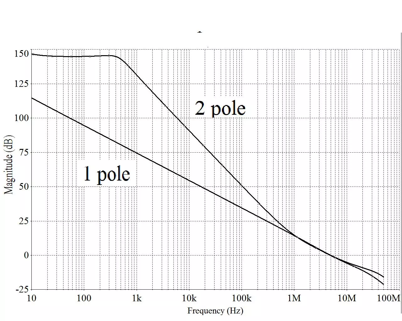
By this time, the astute reader may have realized that a two pole roll off will have two 90º phase shifts (one from each pole) resulting in the maximum allowed 180º phase shift that is permissible for stability. Red flags might be popping into the mind. The secret to successfully implementing a 2 pole compensation scheme is to make it revert back to a single pole roll off having only 90º of phase shift just before the loop gain crosses 0dB. If this can be accomplished, the Nyquist stability criteria will still be met. This is happening and can be seen on the prior graph by how the two pole gain plot overlaps the single pole plot starting around the 1MHz region of the curve. This ensures that there will be ample phase margin to ensure stability. To see the two pole compensated phase plot, refer to the graph on the right
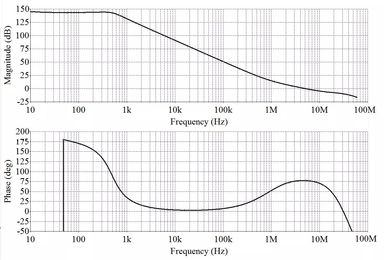
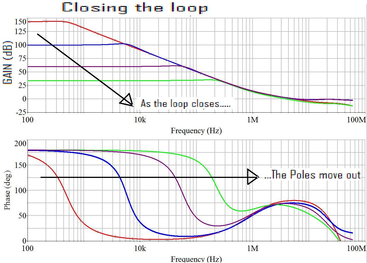
It can be seen that around 1 MHZ, the two pole roll off transitions back to a single pole, and the phase shifts back up to 90º. This device still has 75º of phase margin at unity gain crossover, and stability will be maintained. The 180º of phase shift that exists in-band is never a problem either, because as the op amps' loop is closed, the poles move out, and the associated phase shift occurs later in frequency. What it amounts to is that for any closed loop circuit, (which op amps always operate closed loop) there won’t be any phase shift occurring within the closed loop bandwidth. This can be seen in the following plots that illustrates what happens as the loop is closed.
It can be seen from the plot that as the loop is closed with external feedback, the poles move outward. This little gem of a truth often goes unrealized, which accounts for a lot of the apprehension associated with feedback and high loop gains. People tend to freak out when they hear of 180º of in-band phase shift in an open loop plot, not realizing that as the loop gets closed, this phase shift doesn’t occur within the closed loop bandwidth.
Conclusion: As one navigates the field of op amps in their quest for the perfect device, here are a few things to keep in mind.
- Bandwidth and open loop gain are linked together by compensation. Higher gains always come with higher bandwidths.
- Open loop gain tends to be specified at DC, and will always fall at a rate of 6dB/octave in single pole compensated IC devices.
- Fast slew rates beyond ~10V/µS are not needed for high performance audio.
- Neither are things like 50MHz bandwidths.
- The high bandwidth and associated stability issues are what has given high gain devices a bad reputation in some audio circles.
- Two pole compensation is the ultimate technique for maximizing open loop gain and has the happy side affect of maintaining a reasonable bandwidth.
- Two pole compensation is usually only attainable with discrete op amp designs.
Share it for your friends who like to nerd out


