Op Amp Power Supply Decoupling capacitors and Bypassing.
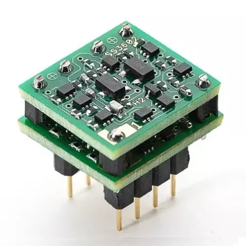
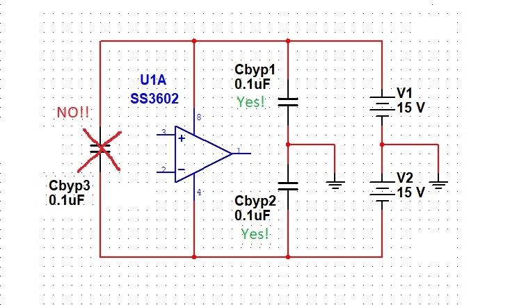
To the right we can see a typical audio op amp, (one of the finest that man kind has ever known, actually) its power connections, and the two power supply bypass capacitors Cbyp1 and Cbyp2. Most op amp manufacturers (myself included) will say that these capacitors should be 0.1uF, and that we should have one capacitor from each power supply rail to ground. These are mandatory, and any designer who does not design-in these capacitors for every op amp, every time, should be flogged with no less than 20 lashes.
Some people will then wonder if we should ALSO have another cap that goes ACROSS the power supply pins (Like Cbpy3) either instead of, or in addition to, Cbyp1 and Cbpy2. The answer to that is no. Having a capacitor across the rails doesn’t properly bypass our audio op amp. These capacitors MUST go from each rail to ground. If we have some perverted “single supply configuration with a pseudo ground” then we must bypass each power rail to the pseudo ground.
If it makes us feel any better about things, we already technically have a power supply bypass capacitor across the rails. Because Cbpy1 and Cbyp2 are essentially in series, and are connected across the rails. Sure, they have a ground connection in the middle of them, but that doesn’t change the fact that they are essentially in series, and are going “across the rails” of the op amp.
Capacitor types and flavors
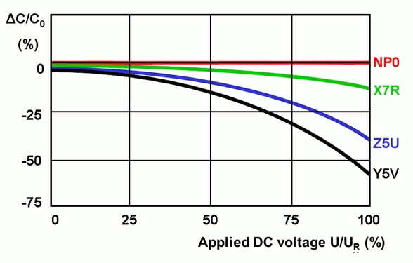
So now that we understand that we need to use 0.1uF capacitors from each power rail to ground, the next question becomes what TYPE of capacitor should we use for these? Ceramic capacitors come to mind, but the problem with ceramic capacitors is that their capacitance will shrink when DC voltages are applied to them. And not just by a little bit. On the graph to the right, we can see that some types of ceramic capacitors will drop in value by almost half if we run them up by their maximum voltage rating.
A fun little side note is that most capacitor manufacturers don’t really talk about this. They just assume that everyone knows. NP0 and C0G ceramic caps do not have any voltage coefficient, and are an excellent choice for this application. The problem is that NP0 and C0G ceramics only tend to come in values of 0.01uF (or 10nF, or 10,000pF) and smaller. Values of 0.1uF do exist, but they will be pricey and physically large. The next best choice is X7R or X5R ceramic. These types of ceramic capacitors have a slight voltage coefficient, but they are the next best thing to C0G/NP0. They are also more widely available in values of 0.1uF, and they will end up costing less. We should be avoiding the Y5V, Z5U, and pretty much all other flavors of ceramic capacitor like the plague.
Film capacitors are also a good choice for our 0.1uF power supply bypass capacitors. They don’t have any voltage coefficient, but they tend to be physically large and are mostly available as only through-hole parts. I tend to be a surface mount guy myself, (and if you ever get some tweezers and learn how to do surface mount, you will never go back to through hole, trust me.) so I typically opt for X7R ceramic in these applications.
Now, if we have a “demanding load” – like if we are using our SS2590 discrete op amps to direct drive headphones like we do in our Aries Headphone Amplifier, and we expect several 10’s or 100’s of milliamps of load current to be flowing, then we may want to consider adding some additional, higher value electrolytic or tantalum capacitors to our bypassing capacitor arrangement.
In this case, I like to use about 100uF or so in parallel with each 0.1uF bypass cap. These should be specifically Tantalum Polymer or Electrolytic Polymer type dielectric. The “polymer” types of electrolytic and tantalum are fairly new, and have much lower ESR (Equivalent Series Resistance) than the standard, “non polymer” flavors have. They also cost a bit more. So if we want to go the extra mile, or if we have a demanding application load current wise, we should look to add some of these to our bypassing capacitor arrangement. These types do not have any voltage coefficient either. Just make sure to hook them up the correct way around as both Electrolytic and Tantalum caps are polarized.
Layout Considerations
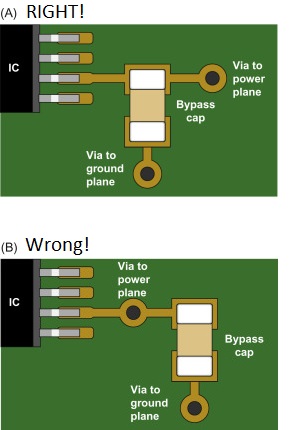
For guys that are designing and laying out their own circuit boards, the way that these bypass caps are routed will matter. The incoming power feed should hit the capacitor first, then go in to the audio op amp and terminate on the power supply pin. We call this routing “Via, Cap, Pin” assuming the power comes up though the board on a via tied to a power plane. The picture to the right shows the right and wrong ways to route this trace. We should also strive not to hit the power pin first with our power feed, and then go on to the bypass cap. (This would be Via, Pin, Cap.) Nor should we “split the difference” and come up with our via, and T off to the power pin and the cap as shown in the picture on the right.
Bear in mind, that what is being said here is from an engineering perspective. Many people will claim that some cap across the rails, or some massive 4700uF bypass caps on every op amp will sound better. And yes. Maybe it does. That is the fun part about all of this. Playing around with things, listening, and figuring out what sounds the best. Audio tends to be a unique blend of science and art. It's just that often times, I am hard pressed to explain WHY any of those things sound better from an engineering perspective. That doesn’t really matter though, due to the "art" aspect of this. If something sounds better, then it's better. Regardless of if we can explain why from an engineering point of view or not.
So now get out there, keep this stuff in mind, and start effing around with your power supply bypass capacitors on your op amp stages! Happy Capping !

Want more content like this?
Just enter your email address below
Share this post to save the world from crappy power supply bypassing schemes.
Check out our other products and gear