Headphone Driver Circuits using the SS2590
So you want to build a headphone amp?
Building a DIY headphone amplifier can be a very fun and rewarding project. Today we will talk about using the SS2590 Pro Discrete Op Amp as a headphone driver circuit.
It may seem odd to suggest using op amps for a headphone amplifier circuit, and believe me, most op amps are not up to the task since they have limited current drive capability. Since the SS2590 can swing a quarter of an amp and be ran from +/-24V power rails, it is well suited to this task using some simple circuits.
Op amps typically want to drive a purely resistive load, and headphones are anything but. Headphones are considered REACTIVE loads, which means that they have considerable inductance from the voice coils, and capacitance from the cabling in addition to resistance from the voice coil wire. And Op amps don't like that. Forcing op amps to drive reactive loads like this will usually cause them to become unstable and oscillate at high frequencies. The secret to tricking an op amp into being stable while driving a reactive load lies in the addition of an extra resistor (Riso) that can be found in the circuits below. These are the same circuits we use in our Aries Headphone Amplifier for the output stage.
Headphone Amplifier Circuit
To the right we can see a typical non-inverting op amp configuration with the addition of Riso for driving headphones. Riso keeps the op amps output from seeing the reactive load presented by the headphones and will ensure that it stays stable. Notice how the feedback resistor (R1gain) is tied to the far side of it, and that Riso is enclosed within the feedback loop. This will force the SS2590 to "drive over" Riso and prevent it from forming a voltage divider against the headphones. It will also keep the damping factor high, and allow the op amp to have a firm grip on the headphone voice coils.
Riso should be a power resistor rated for 3 to 5 watts as it will be subjected to the load current demanded from the headphones. Wire wound types are a good choice for this.
Capacitor Cpole, which is also used to ensure stability and set a bandwidth, would normally go in parallel with R1 gain. With the addition of Riso however, it must be connected a bit differently and be tied from the op amps minus input on one side, and the op amps output on the other. I typically set the value of Cpole to give a cutoff frequency of a few hundred KHZ. In the circuit to the right with the values shown, this works out to be about 234KHZ.
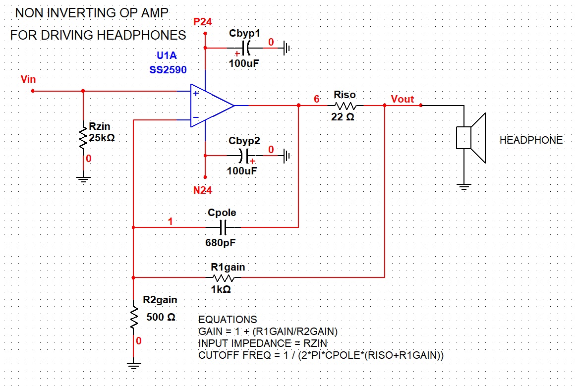
Some other tid-bits about the circuit above is that it has a gain of 3 with the values shown. The gain can easily be changed to suite ones' needs by changing the value of R1 gain. Since headphones are considered a "demanding load" that requires 10's or 100's of milliamps to drive, we have opted to use 100uF electrolytic bypass capacitors (Cbyp1 and Cbyp2) on the power supply rails. Normally we would also like to see some 0.1uF X7R ceramic caps in parallel with these, however the SS2590 pro discrete op amp has these built in, making it unnecessary to add them externally. More about power supply bypass capacitors can be found in this blog entry here.
There will be considerable current flow in the headphone ground as well as the ground side of R2gain. These ground returns should go back to the main power supply revivor capacitors using a star routing scheme.
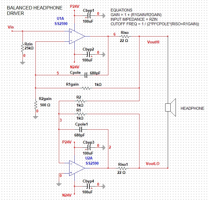
What about balanced tho?
If we want our headphone driver circuit to run in fully balanced mode, the circuit to the right can be used. Its essentially the circuit above with a second SS2590 added that runs in unity gain inversion mode to drive the other side of the headphones. This second inverting op amp also has an Riso and similar gain setting components. Since this op amp just takes the output of the upper one and inverts it, its gain should be set to unity. The values for R1 and R2 accomplish this since the gain of an inverting amplifier is equal to R1 / R2.
A headphone amplifier circuit running in balanced mode (also called "bridged mode") can double the voltage swing into the headphones. This maybe useful if the power supply rails are low or if the headphone impedance is several hundred ohms.

Want more content like this?
Just enter your email address below
Because the world needs to know.
Check out our other products and gear